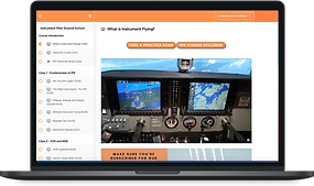
How an Instrument Landing System Works
Updated: Apr 1
The Instrument Landing System (ILS)
An aircraft descends through a thick layer of overcast clouds. The altimeter indicates the ground is getting closer and closer… Suddenly, approach lights appear out of the mist, leading to a wide runway, and the aircraft makes a smooth touchdown.
One of the most satisfying actions a pilot can make is flying an instrument approach to minimum altitudes, and it’s made possible by the Instrument Landing System or ILS. The ILS uses highly directional radio transmitters on the ground that provide an exact approach path for aircraft.
Shooting an ILS Approach is a basic skill in instrument training, and is covered in depth, along with other important topics, in our IFR Ground School.
The ILS Approach Chart
Let’s talk about how the ILS works by looking at an example. We’ll use the approach chart, or plate, that the FAA published for the ILS approach to Runway 31 in Sioux City, Iowa. We won’t get into all the details of the approach plate in this video, we just want to visualize the approach and how the ILS works.

Private pilots know that they can use an array of red and white lights called PAPI or VASI to determine if they are too high or too low on approach. When the aircraft is on the proper approach path, or glideslope, the pilot can see a line of red lights over a line of white lights. If he gets too low the lights become red over red, if he gets too high, it's white over white.
The pilot can adjust the aircraft’s descent angle until the VASI is red over white, to get back on the appropriate glideslope. A VASI works by having each different light send out both red and white indications directionally, and they are oriented so that on the proper glideslope, the aircraft sees red on top, and white below (see left picture below). This overlap which creates the glideslope can be represented by a feather symbol (see right picture below).


Now, we can tell our descent angle by looking at lights located at the runway, but what do we do if the weather limits our visibility? Well, we can replace these lights with radio signals. Both are waves of different frequencies after all, whether we use lights that get picked up by our eyes or radio waves that get picked up by our antennas, the result is the same.
Radio Waves to Take the Place of the PAPI
The glideslope of an Instrument landing System uses two radio transmissions at different frequencies, one at 90 hertz and another at 150 hertz. Think of it as broadcasting two different colors just like the PAPI or VASI does, after all, color differences are also just differences in frequency in the visible light spectrum!
These transmissions are oriented so that they overlap along the proper glideslope. When the equipment on board picks up both signals perfectly overlapped, it tells us that we are on the correct glidepath. Too much of the 90 hertz signal, and we’ll indicate too high, too much of the 150 hertz, and we’ll indicate too low.
These transmissions originate from a series of antennas that are situated on the side of the the runway on the approach end.

They’re right next to the VASI lights, indicated by the “V” in the black circle, which makes sense because as we said they are doing basically the exact same job.

Look at a satellite image of this runway, we can see that the glideslope antenna, right in the middle of the two VASI lights.
The Glideslope Angle
A typical glideslope on an ILS approach is set at a 3° angle of the ground. (This is typically not depicted to scale on FAA plates for visualization purposes). In the airplane, the VOR receiver interprets the signals from the glideslope. When the aircraft is right on glideslope, the indication on the receiver has the horizontal needle perfectly centered (as shown below). If we were to also look at the VASI lights, we’d see red over white.

If the aircraft gets above the glideslope, the horizontal needle will incrementally move below center, and the VASI will eventually indicate white over white. If the aircraft gets below the glideslope, the needle will move the opposite direction and get above center, while the VASI will show red over red. Note that the needle moves incrementally, giving us an idea of how far off center we are, though VASI can only indicate too high, too low, or just right.


The VOR receiver on the left indicates the aircraft is too high, the one on the right too low.
We use these indications to make corrections by chasing the needle, just like we do for VOR navigation: If the needle is above center, we need to climb, or slow our descent, until the needle centers. Once it is centered we keep making adjustments to keep it centered.
One limitation of the glideslope antenna is that because objects can reflect signals from the ground, false glideslopes can be created which have 9 or 12 degree angles off the ground, instead of the usual 3. For this reason, it’s typical to fly an ILS approach by intercepting the glideslope from beneath it, so as to avoid these false glideslopes.
The glideslope provides vertical guidance, but an ILS also provides lateral guidance. This lateral guidance works very similarly: two signals are transmitted from the runway, one on the left at 90 hertz, and one on the right at 150 hertz. These two signals are directed such that they intercept on a course guiding the aircraft down the centerline of the runway. This transmission is called a localizer, and it’s also represented by a feather symbol. We also use our VOR receiver to track a localizer.
The Localizer - Keeping you on the Extended Centerline
The localizer works very much like a VOR. If we drift right of center the needle swings to the left, and vice versa. In order to stay on the localizer and thus the extended centerline of the runway we need to chase the needle again. The localizer antenna is situated at the opposite end of the runway from the approach. The signal starts at the far end of the runway, and then widens out as it gets further away from its origin as shown by the red area on the plate below. By the time the signal reaches the threshold of the approach end of the runway, it is 700 feet wide, or 350 feet on either side of the centerline. This means that an aircraft just 350 feet off center at the runway threshold would see full deflection on the needle, so it’s quite sensitive at this point.
Because of this fixed width at the threshold, and the fact that the localizer transmitter is set up at the far end of the runway, the angle of the transmission varies with the length of the runway. For example, a much shorter runway would have a localizer that would look more like the blue shaded area on the picture below, in order for the width at the threshold to remain at 700 feet. This means that the width of the localizer course a given distance away is not fixed, it is dependent on the length of the runway, and the only constant value is the 700 foot width at runway threshold.

(The red shaded area shows the actual localizer beam for this runway, the blue shaded area shows what the beam would look like at a shorter runway.)
Marker Beacons - Still Around, but not Used as Much
Besides the localizer and glideslope, many ILS approaches provide distance information using marker beacons. This is shown by a football symbol on the approach plate, and is called an outer marker. They are typically located 4 to 7 miles from the runway, and indicate where the aircraft will intercept the glideslope at minimum altitudes. This is the point where the aircraft should normally be configured for the approach. When passing over the outer marker, the aircraft with the proper equipment will hear a beeping noise in the cockpit.

Marker beacons are less and less common in ILS approaches, and distance information is typically provided through DME or GPS. On an approach chart chart the football shape of the marker beacon is found below the localizer feather. It’s shaded on the right side. You’ll always see the right side of the feather shaded on a localizer front course like this, as opposed to the left side which would be on a back course, which is covered in this video.
An ILS approach is flown by tuning the aircraft’s navigation equipment to the correct frequency. The top of the plate lists the frequency for this approach as 109.3. This frequency is for the localizer signal alone, though it is paired with a glideslope signal, at a much higher frequency, that the navigation equipment will pick up automatically. In addition to receiving these two signals, the aircraft will also receive an identification signal, which broadcasts the morse code identifier for the localizer. Here, the identifier is I-SUX, and the transmission will include the morse identifier shown on the plate by the dots and dashes, just as you’d find when identifying a VOR.
ILS Sensitivity and Range
Unlike a VOR, the localizer and glideslope transmissions aren’t broadcast in all directions. They are highly directional, which means that unless you’re lined up with them, you won’t get an accurate signal. Proper indications are only guaranteed within 35 degrees off either side of the runway centerline, out to 10 miles from the localizer antenna, and within 10 degrees off either side of the runway, out to 18 miles.
This means that even when an aircraft is very close to an airport, but outside the coverage areas, the aircraft won’t receive an indication when tuned to the ILS, and an “off” flag or something similar will be displayed. This often happens when being vectored by ATC to the approach course. Once the aircraft enters the coverage area, the receiver will “come alive”.
Putting the localizer and glideslope together, we get a three-dimensional guidance down to the runway. The localizer is beaming a course from its antenna at the back of the runway, and the glideslope is beaming from closer to the approach end. Where they intersect, the aircraft will have both needles centered. Deviating off this three dimensional center will indicate on one or both needles accordingly.
There might also be one or more marker beacons indicating distance and key parts of the approach. On this approach there is an outer and a middle marker. As we continue inbound, the course gets smaller and the needles more sensitive. The middle marker is situated at the decision altitude, typically 200 AGL, where we decide to either continue the descent down to the runway, or if we don’t have any visual cues, we will start a climb out and execute a missed approach.
Knowing the basics of an ILS approach is important, but like most things in instrument training, the devil is in the details! Check out our IFR Ground School and get started on mastering all the tricks of the trade of instrument flying.